Martin Engineering
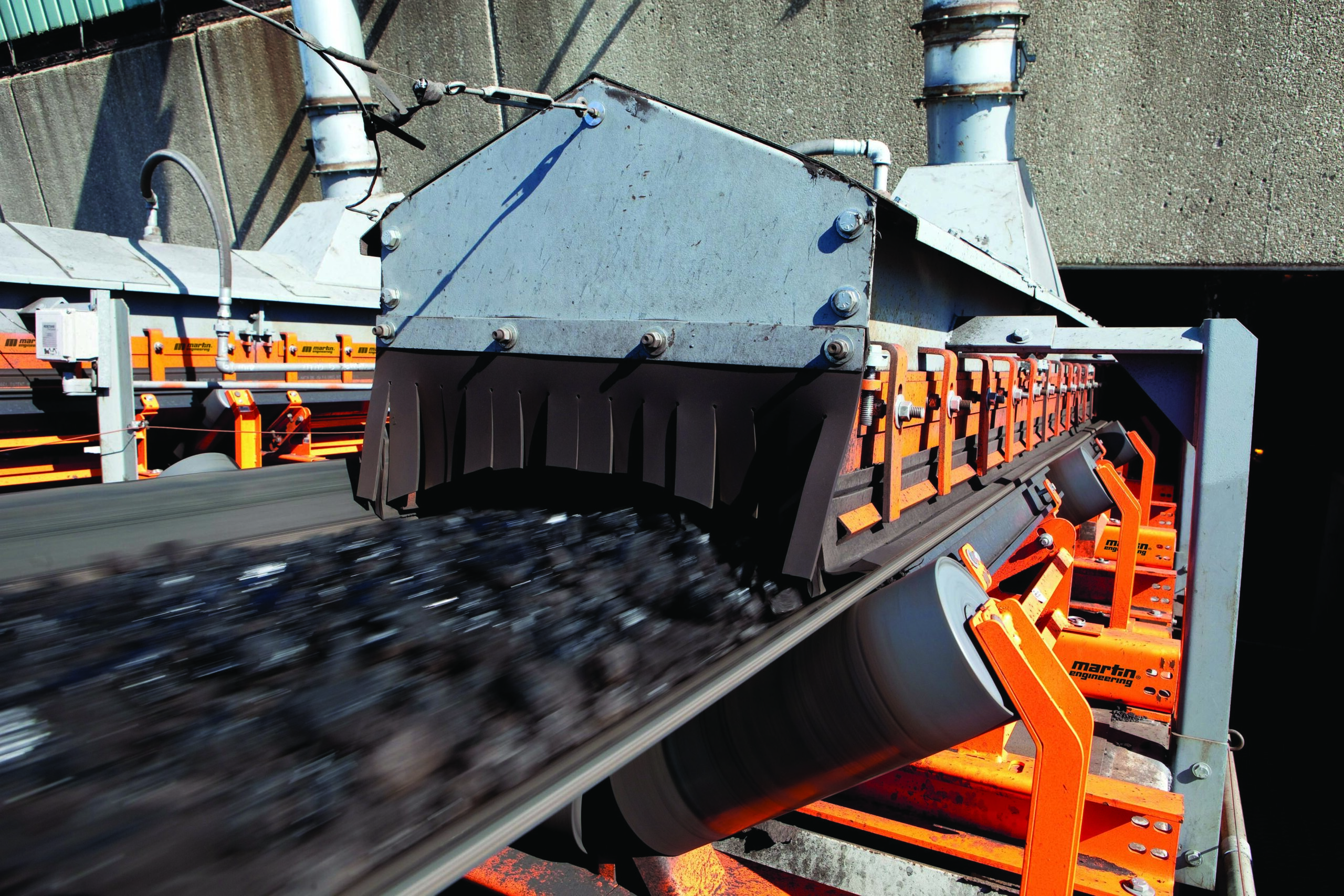
When greater production is needed to meet rising demand or when lower quality raw materials require more tons to be processed per unit of output to retain the same level of production, many operators simply speed up the conveyor. Rather than increasing capacity as intended, speeding up the conveyor often results in reduced capacity, because changes in the trajectory of the discharged material can cause build up and clogging of hoppers or chutes, leading to unscheduled downtime.
More tonnage means more carryback, dust and spillage, degrading workplace safety and increasing labor costs for cleanup. Greater volume and weight could also require a more powerful drive, which may weigh more, requiring structural changes and potentially additional space, limiting access for maintenance.
 Adjustments in belt speed and load volume should be accompanied by an in-depth assessment of the system.
As plant engineers, operators and maintenance mechanics make undocumented or unproven changes, over time, the conveyor operation and physical characteristics can morph the system. In some cases, the proper answer to the question, “Can we increase capacity on the existing conveyor?” should be “No, we need to start over.”
Original Design
Prior to the modification of a conveyor, engineers recommend verifying that the current system is operating in an environment and on an application for which it was originally designed. The existing conveyor may have been repurposed over the years by modifying chutes, adding feed points or changing the slope to accommodate process changes. In situations where the conveyors are many decades old, the original design specifications and drawings could be incomplete or lost.
Conveyor design is an iterative process. Purchasing a conveyor at the lowest capital cost is generally accompanied by significant design compromises. Even if it matches previous conveyor structures, the design is likely to use the maximum loading capacity on the narrowest belt traveling at the maximum speed for the raw material, while meeting only the minimum safety standards and codes. When sold on lowest price, the supplier’s goal is to win the low bid and make it through the warranty period without costly rectifications.
If the goal was to design a conveyor with the lowest cost of ownership over its intended life, it was likely designed with less than maximum loading, a slightly wider belt and the capacity to run at a reasonable speed, while exceeding minimum safety standards and code requirements. The best practice is to re-establish the original design intent and compare it to the existing conveyor.
Conveyor technology changes over time, particularly in belting and calculation methods. Until the 1980s, without the aid of computers and design software, conveyors were designed using hand calculations and experience. It’s amazing how many conveyor designers still use the 1977 5th edition (or earlier) of the Conveyor Equipment Manufacturers Association (CEMA) design guide Belt Conveyors for Bulk Solids, which relies on research from the 1940s.The 6th edition indicated that the hand calculation method was an inaccurate predictor of the actual power needed for proper conveying.
The most recent 7th edition requires predicting power within -0 to +10% of actual. Much research and development for conveyor power requirements has taken place, resulting in several low-cost design software options. [Fig. 1]
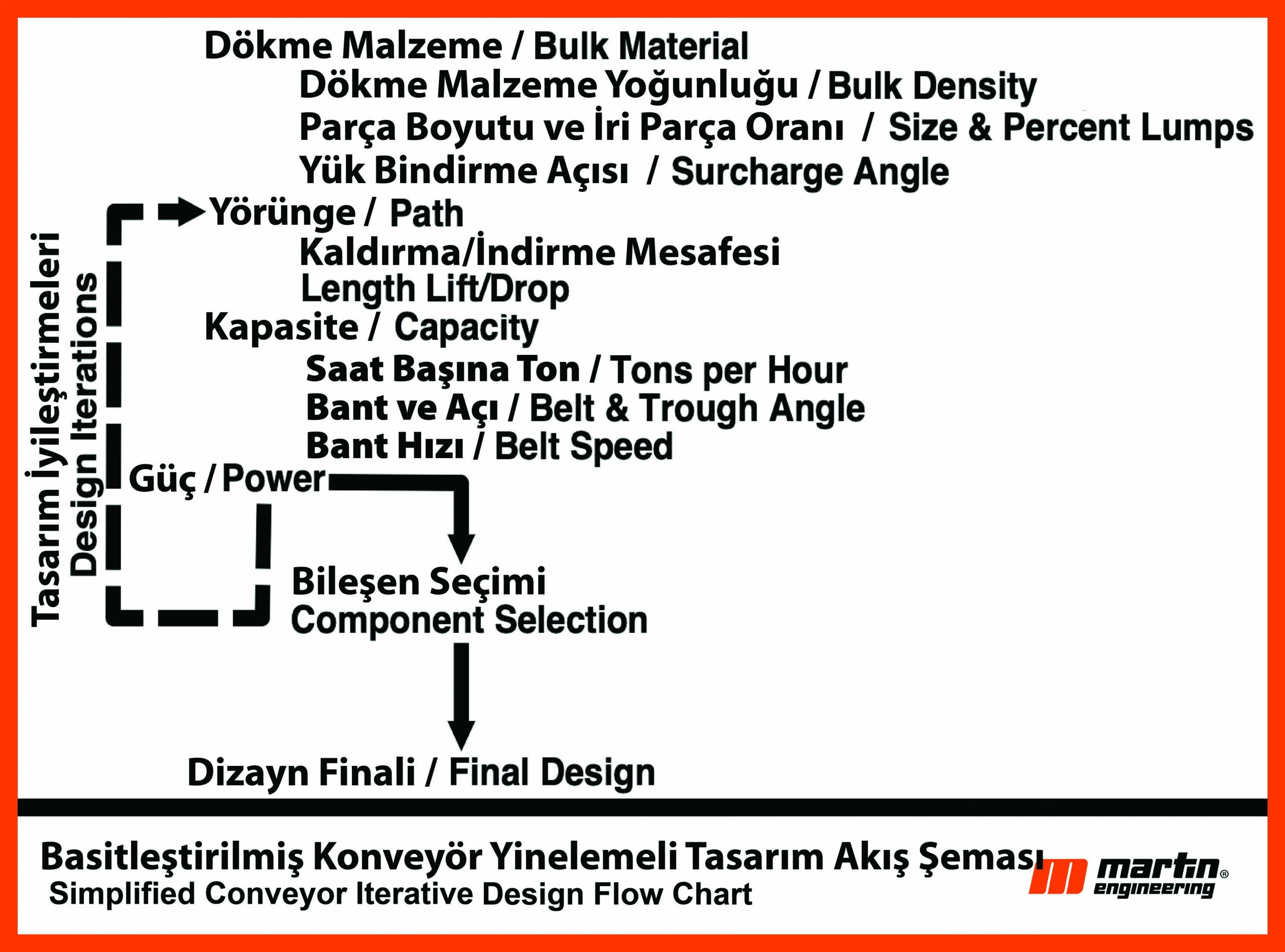
Figure1 – Simplified Conveyor Iterative Design Flow Chart This graphic might show the iterative design intent more clearly.
Upgrade Design
First, define the problem the conveyor upgrade plan is trying to solve. It may seem obvious, but a lack of understanding for the primary reason(s) for an upgrade could cause specifiers to address symptoms rather than root causes. The new design might not address the primary need for a performance upgrade.
For example, if the chutes are plugging or there is spillage, then it might not be a conveyor issue, but instead an operator or maintenance issue. If the problem is belt damage, mistracking or tripping the breakers, it may be due to misalignment of the structure and idlers. Surge loading the conveyor in an attempt to catch up for lost time spent cleaning could result in more spillage.
The Bulk Material
Another critical early step in an upgrade project is understanding the physical properties of the material handled. Knowledge of properties such as solid density, bulk density and particle distribution are crucial to a well-designed conveyor. Original test results for the material are likely out of date due to changes in the sources and variations in the extracted raw cargo over time.
Discrete Element Modeling (DEM) software programs help model the flow of bulk solids through chutes and onto conveyors. Laboratories can perform the tests, or operators can conduct their own basic tests using the information in the CEMA publication, ANSI/CEMA Standard 550 – Classification and Definitions of Bulk Materials.
Component Standardization
It is usually desirable to try to use belting, idlers and other components that are available elsewhere at the site or are common supplier stock items. This may not always be possible, but the capital cost alone should not force a less than optimum design solution. Because increased tonnage might escalate idler loads, rolling components may require a higher load capacity to obtain an acceptable life. Consider the life cycle costs of your design and component selections.
Loading and Transition
One of the biggest contributors to belt damage and the release of fugitive materials is loading the conveyor before the belt is fully troughed, called “loading on the transition.”
Loading on the transition best practices:
• If space permits, rectify the loading so it starts at the second fully troughed idler.
• Vertical curves, if properly designed, are not an issue, but the design calculations need to be verified if the belting or tonnage changes.
• Using bend pulleys for convex curves rather than a spaced array of troughing idlers should be avoided, because it is often a source of spillage.
• Diverter plows and other devices, which tend to force the belt to one side or the other, should be located where the belt has enough distance for returning to running centered in the idlers.
• When loading round particles or operating in wet environments, a belt incline of 5 degrees or less will help create a mass that prevents rolling or fluid cargo from flowing backward toward the tail pulley. The best practice is to load horizontally and then transition into the slope.
• For round shaped material, consider installing curtains along the slope to knock down bouncing particles and allow them to form into a stable profile.
Curtains can control the bouncing or rollback of round particles.
Belt Width and Trough Angle
The trough angle is initially selected based on experience or the existing idlers for standardization. Belt width is selected by calculating the cross-sectional area of the bulk material by assuming a troughing angle, an idler with 3 equal roll lengths and the surcharge angle, lump size and flowability of the bulk solid being handled. There are two important cross-sectional areas to consider, CEMA 100% full and full edge-to-edge. The 100% full area is based on a standard belt edge required to prevent spillover between idlers as the belt sags on the carrying run. The full edge-to-edge loading is used to calculate the maximum potential load on the structure. The best practice is to select the belt width based on 85% of the CEMA 100% cross-sectional area to allow for surge loads, off-center loading or normal mistracking. [Fig.2]
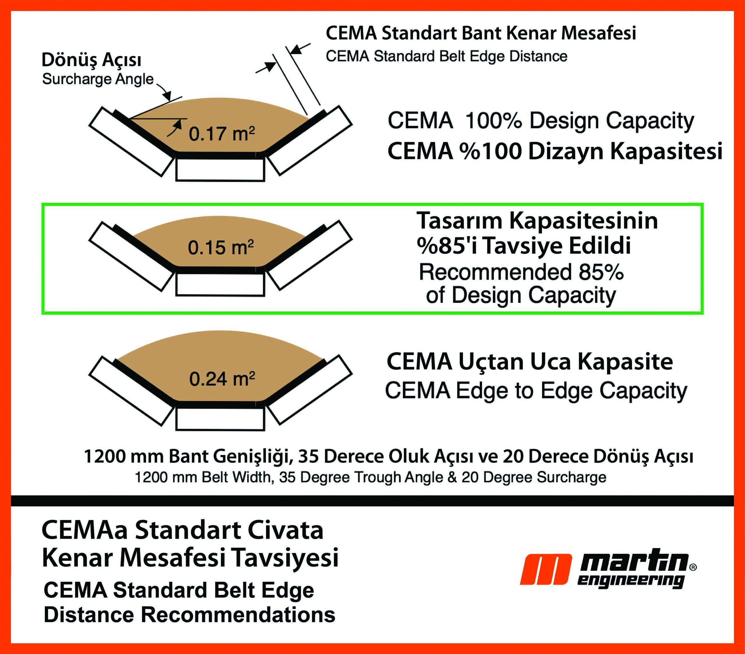
Figure 2 – CEMA Standard Belt Edge Distance Recommendations
If the upgrade is to prevent spillage from mistracking, it may be possible to use a non-standard belt width, because the wing lengths of most troughing idlers allow more room than what is considered acceptable for mistracking belts. It may also be possible to change the standard trough angle or use a custom designed idler to allow for more cross-sectional area. Two common techniques can be incorporated into a new or complete conveyor design to make future upgrades less costly.
The first technique is changing the trough angle of the idlers to raise the capacity by increasing the cross-sectional area. In new designs, consider using 20-degree idlers. Upgrading to 35-degree idlers is a 27% increase in cross sectional area, and going from 20- to a 45-degree trough angle is a 37% increase. Although 35-degree idlers are fairly standard, it is important to note that for retrofit upgrades, going from 35 to 45-degree idlers is only an 8% crosssectional area increase. [Fig. 3]
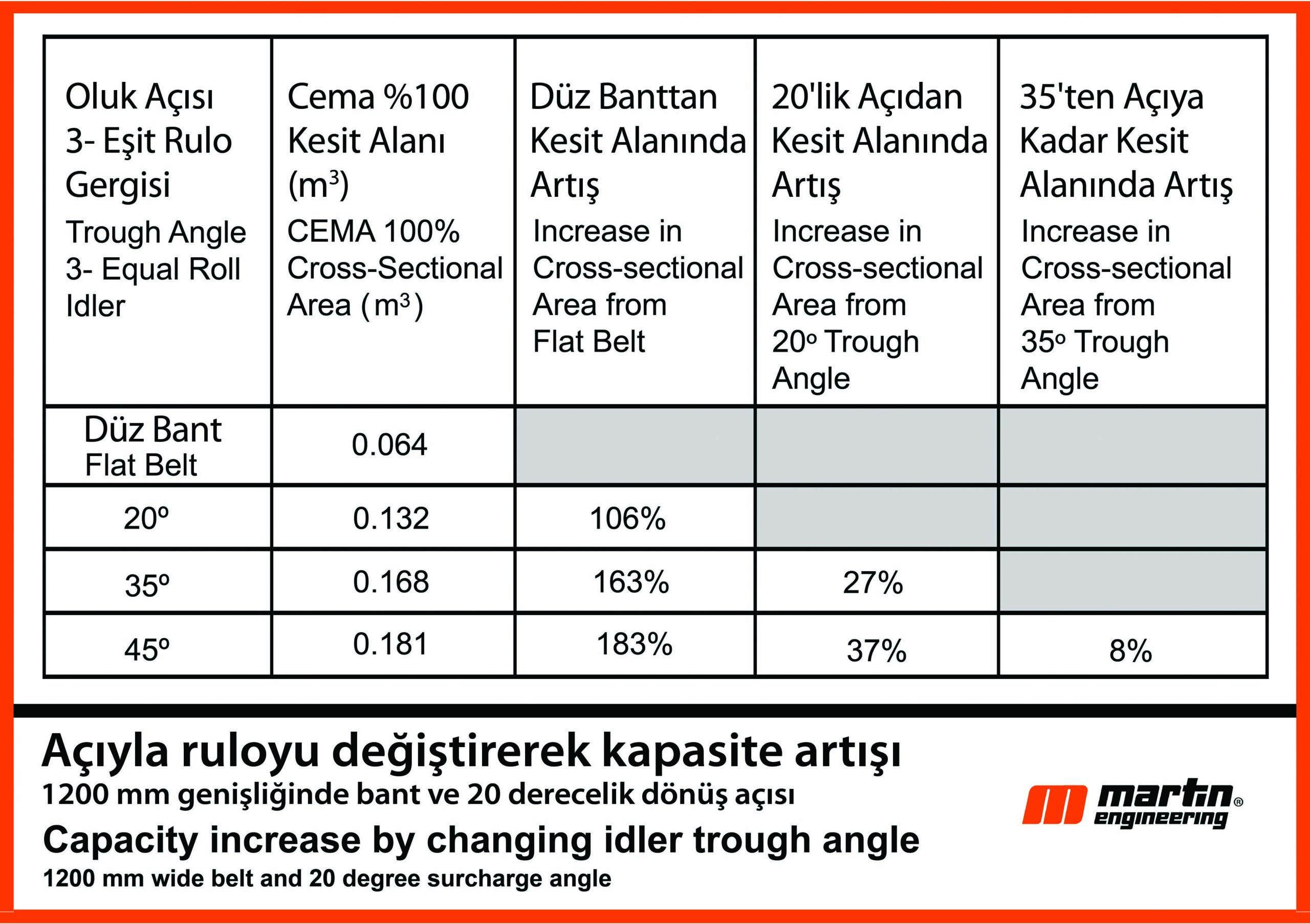 Figure 3 – Comparison of capacity increase by changing idler trough angle (1200 mm wide belt and 20° surcharge angle)
The second common technique for new construction is to design the structure for the next wider belt width and use CEMA widebase idlers.
The mounting dimensions of the wide-base idlers allow for a future replacement with a wider belt. For example, if the structure for the 1200 mm (48 in.) wide belt and 20-degree surcharge angle using 35-degree trough idlers was designed for wide base idlers, the belt width could be increased to 1400 mm (55 in.), resulting in a 33% capacity increase with the same trough angle and belt speed. Changing from a 35 to 45-degree trough angle and the wider belt and idlers would result in a 90% increase in cross-sectional area. This method is not often used, because there is resistance to increasing capital cost for a wider and higher load-bearing structure, higher material mass and larger drive. However, it is an excellent approach if there is an expectation of increasing capacity in the future.
Belt Speed
CEMA provides some guidance on belt speeds for different classes of material in chapter 4 of Belt Conveyors for Bulk Materials 7th Edition. Generally, a wider belt operating at a lower speed will reduce fugitive material release, since the potential for fugitive material release is directly proportional to belt speed and capacity. The lower CEMA recommended belt speeds should be used in the first iteration of the design. Then additional iterations can be tried by changing the belt width, trough angle and belt speed to arrive at a reasonable solution.
Discharge Chute
For a capacity increase, the discharge chute will need close review. The trajectory path should be plotted so that the stream of material impacting the chute does not create a situation where there is zero or negative vertical velocity on impact with the chute. If the material can stay suspended at the impact location, it will increase the chance of buildup and blockage of the chute. If the angle or liner is changed, it must not create a slow flow situation where material backs up and accumulates in the chute. The discharge chute cross sectional area should be a minimum of 4 times the cross-sectional area of the loose bulk solid.
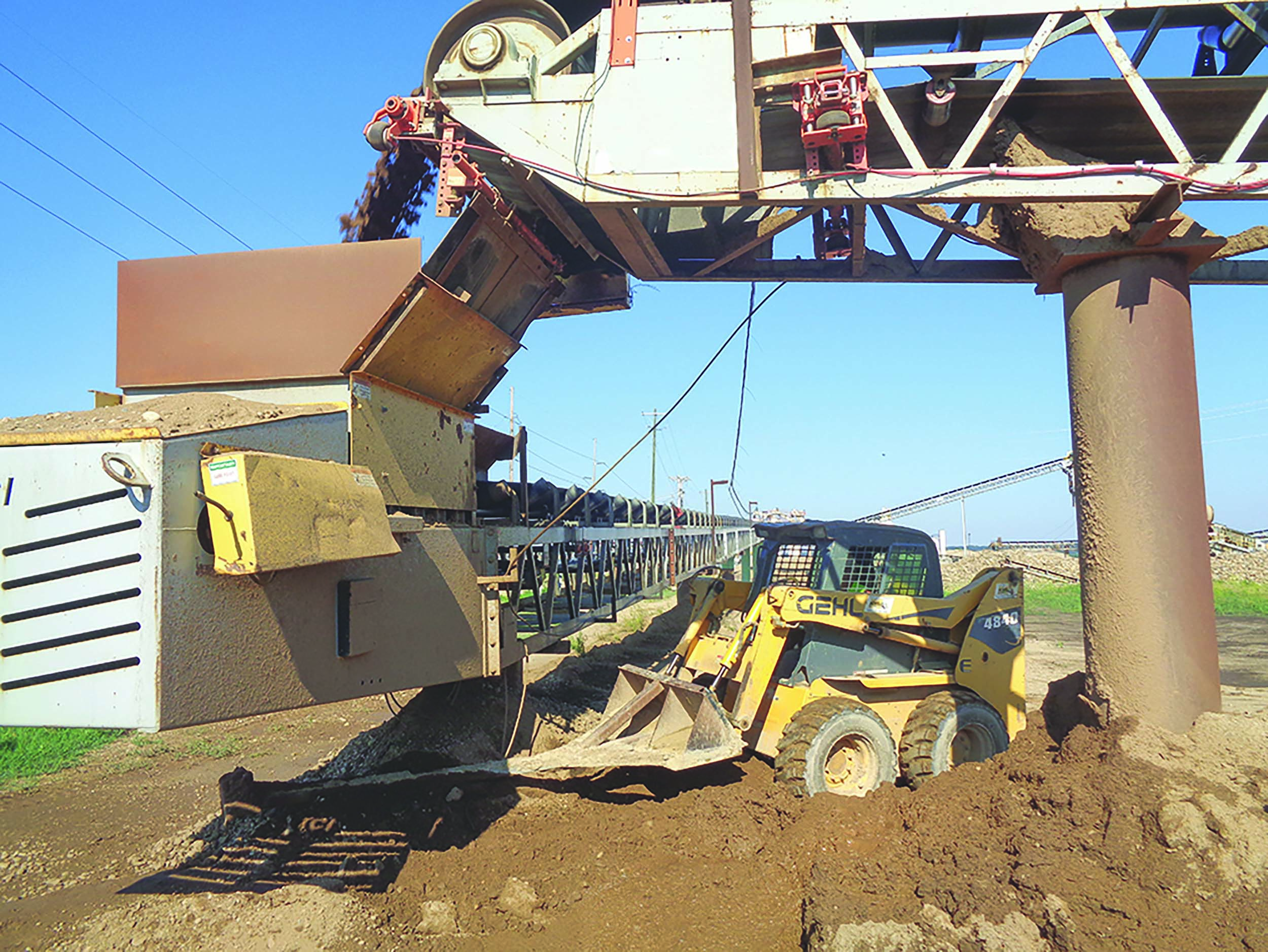
Raising belt speeds and volumes have consequences for transfer chutes and cleanup.
Receiving Chute
The design of the loading chute and skirtboards requires close attention to detail to minimize fugitive material release. CEMA uses 2/3 of the belt width for the inside dimension of the loading chute skirtboards, regardless of belt width. Idler fouling and spillage can happen when uneven loading causes the belt to drift to such a degree that there is an opening between the inside of the chute wall and the edge of the belt where material can escape. Best practice in design considers the amount of allowable mistracking plus the thickness of the sealing system to determine the distance from the edge of the belt to the outside of the skirtboards as the minimum dimension on each side. [Fig. 4]
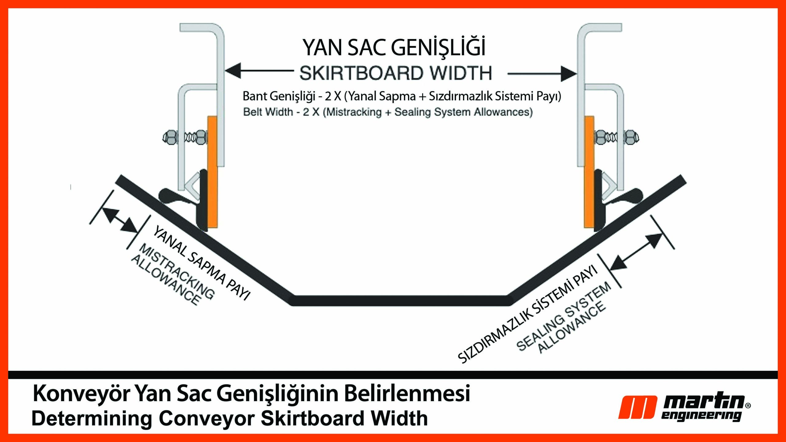
Figure 4 – Mistracking Allowance + Sealing System Allowance x 2 = Skirtboard Width
Maintenance Access
If you upgrade your capacity but can’t access it for maintenance or cleaning, what have you accomplished? This detail is often overlooked. Any upgrade plan should include work platforms and upgraded access. Make sure all the old piping conduits and unnecessary structures are removed. Evaluate guarding and lighting to make inspections easier and more accurate. Provide the necessary power, compressed air or vacuum utilities needed for maintenance or cleaning.
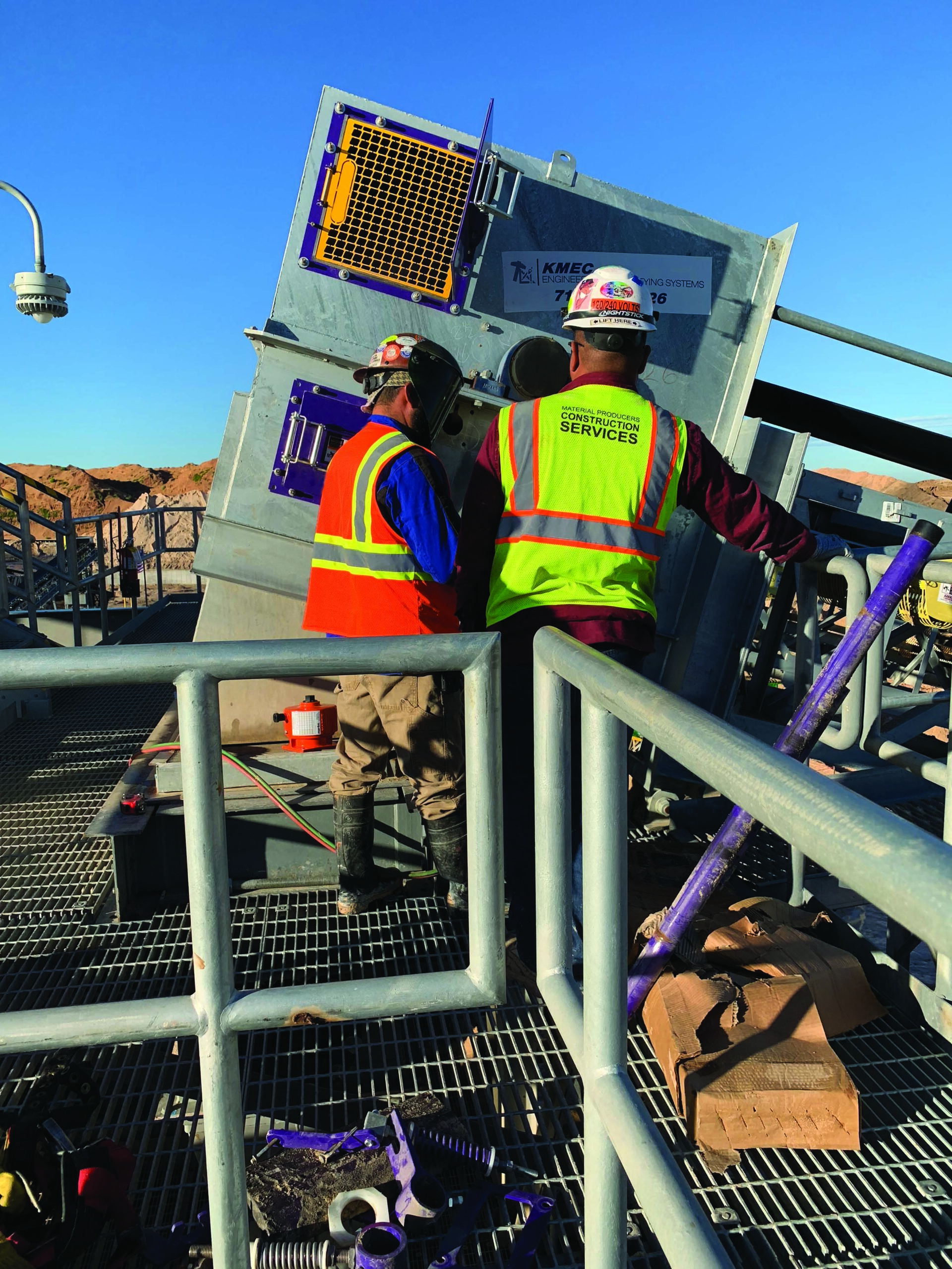
Having safe and available access to components is part of design best practices.
Conclusion
There can be a large benefit to upgrading when the entire system design is considered. There should be an expectation of increased productivity. Additional benefits should include reduced fugitive material release by improved passive dust control and belt cleaning, saving on maintenance time due to improved access and a reduction in safety incidents due to reduced cleanup and maintenancefriendly changes.


