")
Motena Takalimane, Indresan Govender, Aubrey Njema Mainzas
University of Cape Town, Department of Chemical Engineering
Abstract
The use of liners and lifters can influence the trajectory of charge and thus the frequency of contact of the particles with one another and the energy with which they impact the shell and other charge media. They are also fitted to enhance the grinding efficiency by encouraging high-energy impact for a coarser product size and cascading, which encourages abrasion and attrition breakage for finer sized particles. Information on the role of lifters and liners is limited, especially considering the complex nature and workings of tumbling mills. This is where Positron Emission Particle Tracking (PEPT) is useful since it allows for the tracking of a single labeled tracer particle in a lab scale tumbling mill. This non- invasive technique can be used in opaque systems such as tumbling mills without disturbing the motion of the charge. It also extends itself to wet and dry milling, but for the current work PEPT was used under dry conditions and the tracer was labelled with the radionuclide 68Ga, in a mill charged with 5 mm mono-sized glass beads and its trajectory was recorded and analysed. Lifters with differing face angles, mill speeds and charge filling degrees were investigated and the resultant influence of lifter face angle on the location of the Centre of Circulation (CoC) and velocity profile of the charge was determined. Previous work looked at lifter height and the role of lifters can be extended to lifter spacing.
1. Introduction
In the minerals processing industry, comminution takes place in a series of crushing and grinding processes. Crushing would precede the grinding such that the feed material is reduced to a size that will allow the liberation of valuable minerals and unwanted gangue is achieved (Wills, 2006). To encourage efficient grinding, lifters and liners are fitted to the mill shell because of their influence on the trajectory of charge, which is strongly related to the milling efficiency (Makokha et al., 2007). Traditionally they are also fitted to provide protection for the mill shell from hard impact and any contact the charge may have with the shell (Powell et al., 2006). Lifters have been known to assist with extending the liner life by acting as a cushion from the hard impacts of grinding media and ore as well as transferring the energy from the mill as it rotates, to the charge to achieve grinding (Rezaeizadeh et al., 2010). With prolonged exposure and contact to the grinding media, the lifters will become worn as the face angle alters. Thus, wear can be described as the loss of material due to this contact and frictional interactions (Rezaeizadeh et al., 2010), where a 10 to 20 % loss in mass deems the liner unusable and ready to be changed (Makokha et al., 2007).
Work done to investigate the influence of lifter face angle on charge characterisitics has been carried out by several authors. Rogers et al., (1982) used a 0.91 diameter and a length of 1.52m using different liner designs; Powell (1993) studied charge motion in tumbling mills using X-ray to track the motion of charge in a lab scale tumbling mill; Hlungwani et al., (2003) carried out experiments using square and trapezoidal lifters to validate DEM simulations; Rezaeizadeh et al., (2010) used a 3D mill, lined with equally spaced lifters of differing number of rows (15, 30, and 60), load levels (10, 15 and 26 %) and a lifter face angle of 14.5 ˚ and Kalala et al., (2008) showed how the life of a liner can be extended by adding 50 mm bars to increase the height of worn lifters to demonstrate the effect of liners on charge and media impacts. In recent years, discrete element modeling (DEM) has gained a lot of attention as a method to study charge motion in tumbling mills. Work done by Cleary (2001) and Pérez-Alonso and Delgadillo (2012) validated 2D DEM results using digital image analysis of charge descriptors such as velocity profiles, shoulder and toe angles. Later, Cleary et al., (2003) also used DEM accompanied with experimental work on a lab scale tumbling mill to predict the accuracy of DEM models. Kallon et al., (2011) investigated the circulation rate of charge in a lab scale tumbling mill with the help of PEPT
In the present work, Positron Emission Particle Tracking (PEPT) was used to study the influence of different lifter face angles on the trajectory of particles as described by charge descriptors such as Centre of Circulation (CoC) and tangential velocity at different mill filling degrees and mill speeds. Relevant charge kinematic descriptors, which are influenced by lifter face angle were extracted and analysed.
2. Material and Methods
Positron Emission Particle Tracking (PEPT) is a technique, which has been developed to track a single particle, which has been labeled with a radionuclide (Govender et al., 2004). PEPT was adapted from Positron Emission Tomography (PET), which has been used in medicine to determine body metabolism and drug design development (Fan et al., 2006). It has shown to be an extensively important method in studying the behavior of engineering related systems such as granular material in systems such as mixers and fluidised beds (Parker et al., 1997). An earlier limitation of investigating opaque systems and observing flow phenomena in three dimensions was made possible using PEPT (Barigou, 2004). About 50 % of the energy emitted from the labelled particle is able to penetrate through 11 mm of steel or 30 mm of aluminum, validating that PEPT can be used to investigate motion within vessels, which have previously been deemed to have thick walls (Bridgewater et al., 2004).
A single particle was labelled with a radionuclide (18F, 64Cu, or 68Ga), which was placed into a system before tracking is begun. This particle is called the “tracer”, and it was chosen such that it has the same properties as the bulk particles (Fan et al., 2006). Information gained from tracking and observing the behaviour of this single particle can be used to infer the behaviour of the bulk particles (Barigou, 2004). As the tracer particle was tracked in the system, a β+ is emitted and once it comes into contact with an electron cloud, annihilation takes place. Upon annihilation, two backto- back gamma (ɣ) – rays are released each travelling at 180 ˚ with energy of 511 keV (Barigou, 2004). When the gamma rays are detected in coincidence, the two detection points form a line of response (LOR). This LOR is an indication that the event occurred along the line. As more and more of the LOR’s are mapped, tracking of a single particle is made easier since the LOR’s are recorded in chronological order (Cole et al., 2012).
A 300 mm diameter lab scale mill was used for this work, with 20 lifter bars made from aluminum. Four lifter angles were investigated at varying mill speed and charge filling degrees. Experimental details are shown in Table 1 and the lab scale mill used in this work and how it fit into the PEPT camera’s field of view (FOV) is shown in Figure 1. The lifter face angles investigated are shown in Figure 2, with their width and height also given.
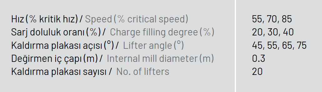
Table 1: Experimental conditions for PEPT work
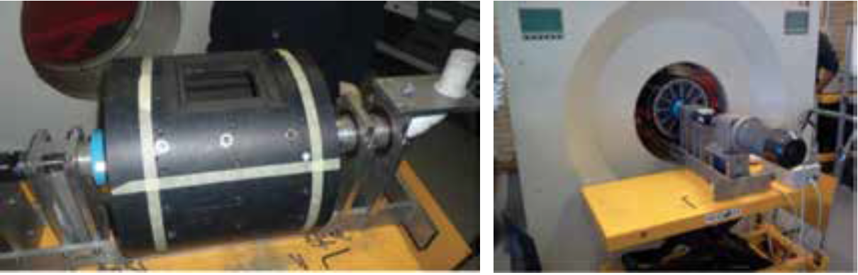
Figure 1: Picture of the 300 mm diameter tumbling mill (left) and the mill placed in the field of view (FOV) of the PEPT camera (right).
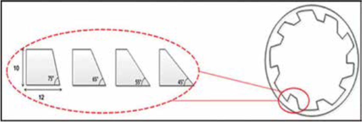
Figure 2: Schematic of the lifter bars placed in the tumbling mill.
3. Data analysis
The Centre of Circulation (CoC) is said to be the point about where the charge seems to be circulating (Powell & Nurick, 1996). If a line is drawn along the CoC it makes it easier to understand the velocity profile exhibited by the charge. Powell and McBride (2004) showed that the CoC is identified by the intersection of equilibrium surfaces; the vertical and horizontal surfaces as shown in Figure 3. The velocity profile was analysed for the region between the mill shell and the CoC (bulk bed region).
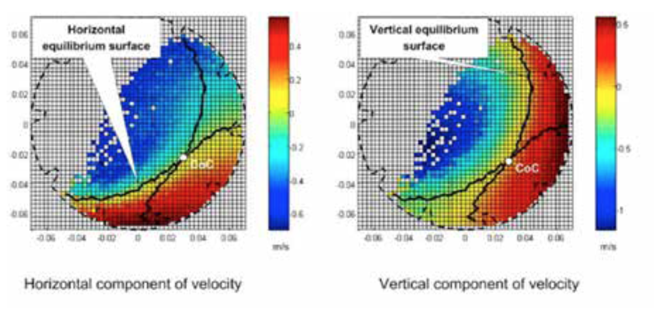
Figure 3: Intersection of the horizontal and vertical equilibrium surfaces to locate the CoC (After Powell and McBride, 2004)
The position of the CoC varied with the changes in lifter face angle at different speeds and mill charging levels as shown in Figure 4. No definitive trend can be seen when the mill speed was varied from 55 to 85 % of critical. The general trend when the mill filling degree was increased from 20 to 40 % was a shift towards the mill centre from the periphery of the mill.

Figure 4: Relative positions of the CoC at different mill speeds and charge filling degrees.
An increase in the mill speed as the lifter face angle was altered displayed higher velocities for the charge in free flight as shown in Figure 5. The hot colours represent particles with higher velocities, whilst the cool colours depict charge at lower velocities. Moving across, as the lifter angle became less steep, higher velocities were not prominent. As the mill speed was increased for all lifter face angles, more of the charge experienced higher velocities with the charge impacting on the mill shell.
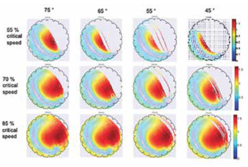
Figure 5: The velocity profile as the mill filling is increased for the different lifter face angles.
The relative magnitude of the tangential velocity can be seen in Figure 6, where a radial line through the CoC displays the change in direction of the charge on either side of the CoC. The profile as seen along the radial line is also shown at the different lifter face angles for 70 % of critical speed.
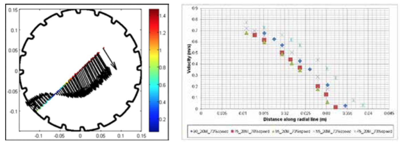
Figure 6: Tangential velocity of charge for a radial line through the CoC and the relative velocity magnitudes along the radial line.
To gain a better perspective of what is taking place as the lifter face angle was changed at different mill speeds; the profiles are shown in Figure 7. At the higher mill speed settings, there appears to be minimal changes to the velocity at distances closer to the mill shell. Noticeable influences are observed at distances closer to the mill centre. For 55 % of critical speed, there lifter face angle has the greatest influence at all distances. The velocity increases from 45 to 75° and then decreased from 75 to 90 °.
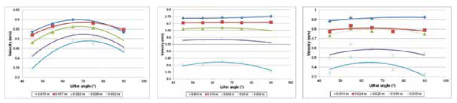
Figure 7: Velocity profiles at 55, 70 and 85 % of critical speed and constant charge filling of 30 % for all the lifter face angles.
4. Conclusions
PEPT proved to be a useful tool for investigating charge characteristics and providing information that can be used to evaluate the influence of lifter face angle on charge trajectories.
It was found that lifter face angle has no definitive influence on the CoC with increase in mill speed. There is a general move from the mill centre towards the mill shell. This can be attributed the mill expansion with increasing mill speed. The converse was observed as the mill charge filling degree was increased, where the CoC position was seen to shift from the mill shell towards the mill centre. At the lower mill speed setting it was observed that changes in lifter angle influenced the velocity profile.
Acknowledgements
The authors would like to acknowledge the Centre for Minerals Research at the University of Cape Town, assistance of the staff at iThemba Labs and Anglo American for financial support for this work.
Referanslar
Barigou, M. (2004). Particle Tracking in Opaque Mixing Systems: An Overview of the Capabilities of PET and PEPT. Trans IChemE, Part A, Chemical Engineering Research and Design. 82: 1258- 1267.
Bridgewater, J., Forrest, S. & Parker, D. J. (2004). PEPT for agglomeration? Powder Technology. 140: 187-193.
Cole, K. E., Buffler, A., van der Meulen, N. P., Cilliers, J. J., Franzidis, J-P., Govender, I., Liu, C. & van Heerdan, M. R. (2012). Positron emission particle tracking measurements with 50 micron tracers.
Chemical Engineering Science. 75: 235-242 Fan, X., Parker, D. J. & Smith M. D. (2006). Labelling a single particle for positron emission particle tracking using direct activation and ion-exchange techniques.
Nuclear Instruments and Methods in Physics Research A. 562: 345-350. Govender, I., Mc.Bride, A. T. & Powell, M.S. (2004). Comparisons of PEPT derived charge features in wet milling environments with a frictionadjusted DEM model.
Society of Experimental Mechanics. 44: 593-607. Hlungwani, O., Rikhotso, J., Dong, H., & Moys, M. H. (2003). Further validation of DEM modelling of milling: effects of liner profile and mill speed.
Minerals Engineering. 16: 993-998 Kalala, J. T., Breetzke, M. & Moys, M. H. (2008). Study of the influence of liner wear on the load behaviour of an industrial dry tumbling mill using the Discrete Element Method (DEM). International Journal of Mineral Processing.
86: 33-39. Makokha, A. B., Moys, M., Bwalya, M. M.& Kimera, K. (2007).
A new approach to optimising the life and performance of worn liners in ball mills: Experimental study and DEM simulation.
International Journal of Mineral Processing. 84: 221-227. Parker, D. J., Allen, D. A., Benton, D. M, Fowles, P., McNeil, P. A., Tan, M. & Beynon, T. D. (1997).
Developments in particle tracking using the Birmingham Positron Camera.
Nuclear Instruments and Methods in Physics Research A. 392: 421-426.
Powell, M.S. & McBride, A. T. (2004). A three-dimensional analysis of media motion and grinding regions in mills. Minerals Engineering. 17: 1099-1109.
Powell, M.S., Smit, I., Radziszewski, P., Cleary, P., Rattray, B., Eriksson, K. & Schaeffer, L. (2006) The Selection and Design of Mill Liners. In: Kawatra,
S. K. Advances in Comminution. Colorado, USA: Society for Mining, Metallurgy, and Exploration, Inc. (SME).
Rogers, R. S. C., Shoji, K., Hukki, A. M. & Linn, R. J. (1982). The effect of liner design on the performance of a continuous wet ball mill. XIV International Mineral Processing Congress. Canada


