

Martin Engineering
Conveyor systems are the lifeblood of a wide variety of bulk material handling operations, including mining, coal and ore processing, as well as aggregate and cement manufacturing. In today’s modern systems, loads up to ever-higher volumes are expected to be transported at higher speeds. While user expectations for the safe, convenient and reliable transportation of bulk cargoes by minimizing leakage materials have increased, traditional applications in the determination of conveyor characteristics and conveyor design processes have become unable to meet these expectations.
Belt conveyors have been mishandled through overloading, overuse or neglect. Sometimes all three of these mistakes are made at once. In fact, designers and manufacturers have done such a good job of providing very robust systems that continue to operate under all adverse conditions that conveyors have come to be seen as mass-produced goods that can be purchased by the kilo, rather than systems designed by carefully combining hundreds of different components.
Starting from this point of view, many business owners see conveyors only as extremely simple equipment that moves bulk cargoes from Point A to Point B at a specified speed. In reality, conveyors are complex systems that interact with almost all key processes. Therefore, the effects of using shortcuts in the design and feature determination stages on safety, production efficiency and the environment are extremely common and widespread. In these circumstances, trends involving designs for lower risk, better sustainability, and lower life cycle costs come to the fore, and design decisions affect the future performance of the conveyor system as well as its initial use.
Unfortunately, it has become standard practice to buy the lowest priced product instead of considering life cycle costs. However, this practice, which is extremely flawed, usually causes the funds allocated for the necessary design elements to be transferred to the operating budget within the capital expenditures. These budget changes are due to the high maintenance cost of the low-cost design, the emergence of modification requirements as changing needs or conditions arise, or the fact that the funds needed to fix deficiencies in the original equipment were never actually allocated.
Factors such as improper specification of conveyors, development of designs solely to meet price targets, and concealed financing irregularities all contribute to a multitude of problems. These problems cause high costs due to low efficiency, accidents, pollution and legal processes that can last for the lifetime of the conveyor. The ten-point expert-edited list displays the most common design mistakes that can degrade a conveyor’s safety, cleanliness, and efficiency over time. Thus, it is aimed to prevent plant owners and plant managers from falling into the trap of focusing only on the purchase price when making decisions.
1. Lack of knowledge about the properties of the materials used in conveyor production
It has been a common practice for decades to use only bulk density and bulk angle to describe bulk cargoes. The Conveyor Equipment Manufacturers Association (CEMA) receives numerous requests for the preparation of tables containing all bulk materials. This expectation stems from the misconception that it is possible to fit all derivatives of bulk materials into a guidebook, and it is an approach that has significant problems.
One of the most important dangers arising from not knowing the bulk material well is that the most basic condition, tonnage, is not given enough priority. The main purpose of the conveyor
is to transport X tons of material from one place to another in an hour. If this goal is not effectively achieved, all other conditions become secondary. CEMA 550: Characteristics of Bulk Cargoes lists eight different bulk densities for coal, ranging from ~ 600 to 980 kg/m3. These data show that the average bulk density can vary greatly as: ~790 + 190 kg/m3. In this case, if the system is designed over the average value, +25% more or less design can be made on the basis of hourly transported material.
Moreover, the stack angle of these eight coal derivatives listed varies between 27-45°, i.e. +9° from the average. Designing the inclination of the hoppers or chutes to an average value can result in the bulk material not flowing at all, or flowing freely without being adequately controlled by the chute geometry.
The typical set of tests required to characterize a given bulk load costs around $30,000, while the estimated downtime on the system is around $1,000 per minute. Even just one-time chute clogging during the lifetime of a conveyor system can pay off for testing.
 Copyright © 2020 Martin Engineering
Interaction between conveyor belt, chute liner and bulk material, It is being measured in a dry abrasion tester using the 3-body abrasion technique.
Similar arguments can be made for many other values critical to reducing future operating costs. For example, in bid requests, lump size and percentage of fines are often misrepresented, resulting in disputes over contract performance.
Suggestion: Test samples from the actual bulk to be transported over the full range of expected moisture content and compression pressure, and use the data from these tests to design the conveyor system.
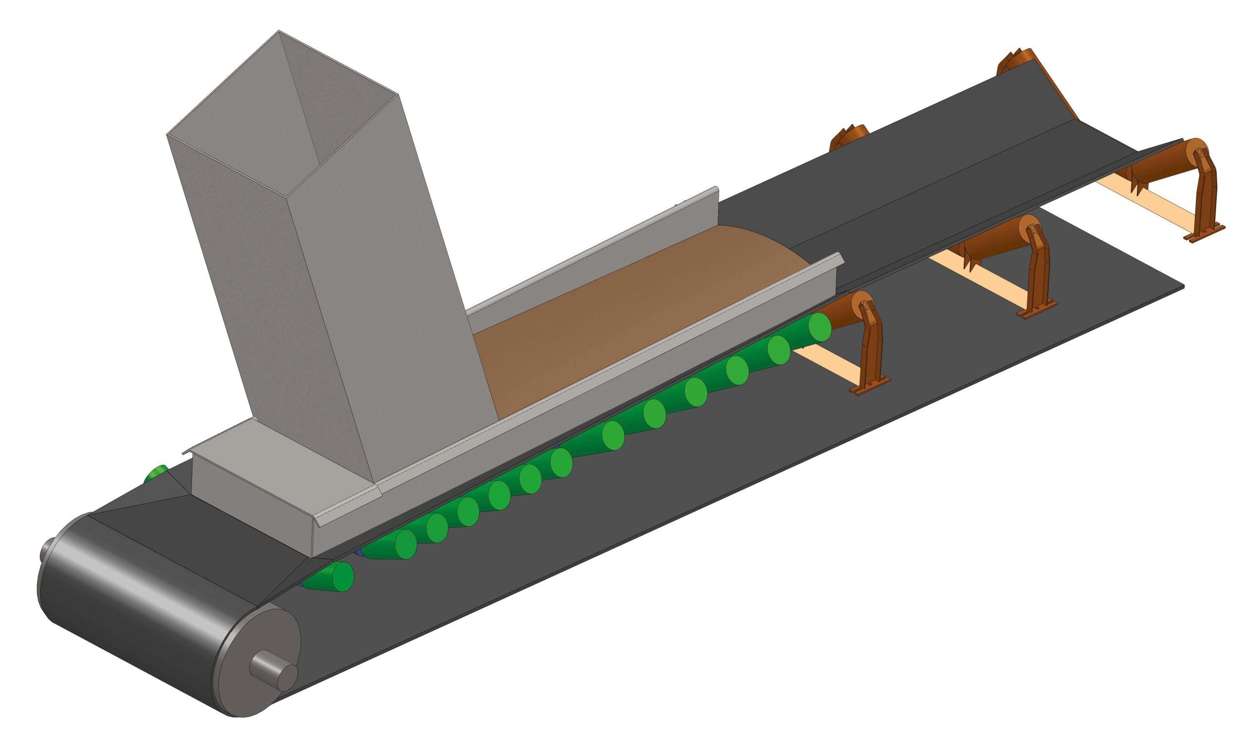
2. Loading During Transition
Saving the overall length of the conveyor by loading where the belt goes from flat to corrugated is a common practice to meet price targets. Another approach used to shorten the conveyor to meet price targets is a design technique called the half letter box. If transition loading and half letter box applications are used together, belt wear, chute wear and the amount of debris may increase.
 Copyright © 2020 Martin Engineering
The transition region is the region where the flat belt becomes corrugated.
Reducing conveyor length by one meter or more in both the loading and unloading zones and saving approximately two meters of belt can lower the cost per conveyor by $15,000 to $20,000. Additional savings can also be achieved by downsizing the building housing the conveyor.
However, these cost-saving measures come at a cost. Many designs that use transition loading and half letterbox transition alone or in combination soon develop operational problems. The primary problem is the problem of leakage material in the form of debris and dust. The belt transition surface between the straight tail pulley and the first fully corrugated pulley is a complex, 3-dimensional surface that is difficult to model, affected by variations in belt tension with loading variations. Accurate modeling of this surface is nearly impossible. In this case, the final sizing operations must always be done in the field in order to fit the chute onto the belt, increasing the cost. In principle, on-site manufacturing is considered to be 10 times costlier than factory manufacturing.
If loading or half-groove techniques are used in the transition, the chute should start parallel to the tape in the transition and then form a convex curve to follow the tape in the full letterbox section. The bending action required for this creates a point where the fines become trapped, facilitating the wear of the liner and the duster, ultimately causing compression damage to the belt. The characteristic “halfmoon” shaped wear zone of the liner and the skirtboard above the rollers in the most turbulent loading zone cause a large amount of material leakage. Often these leakage materials need to be manually cleaned afterwards.
The savings of $15,000 to $20,000 quickly melt away as additional cleaning costs arise, more frequent seal and liner maintenance is needed, and belt life is shortened. During the feature identification and design phase, numerous other design and maintenance issues arise due to such design decisions.
Suggestion: Use the full trough transition distance recommended for the belt type and belt width. Begin loading after the first fully corrugated reel.
3. Using the Lowest Drum Diameters
The diameters of the conveyor’s main drums are usually selected by the belt manufacturer based on the minimum recommended value, based on belt tension, to extend belt and skelp-end life. The possibility that these drum diameters may be too small to allow other components to function properly is often overlooked. When using smaller drive drums, it is often necessary to use a deflection drum to enlarge the winding angle and provide the necessary friction to drive the conveyor. The deflection drum must be close to the drive drum to enlarge the winding angle. This limits the space available for cleaning the belt and head pulley and can cause serious buildup on the baffle pulley, which is the first rolling element to come into contact with the dirty side of the belt. When using smaller main drums, the space between the upper and lower parts of the belt is often insufficient for critical accessories used to protect the belt and provide good centering.
Suggestion: Best practice is to choose a drum that is at least 600mm in diameter, or at least one size above the minimum size recommended by the belt manufacturer.
4. Conveyor Designs Do Not Allow Access, Insufficient Access
Examples of failure to provide appropriate access in conveyor design are so numerous that an article could be written on this topic alone. One side of the conveyors is usually kept very close to the wall and maintenance workers have difficulty entering from the wall side.
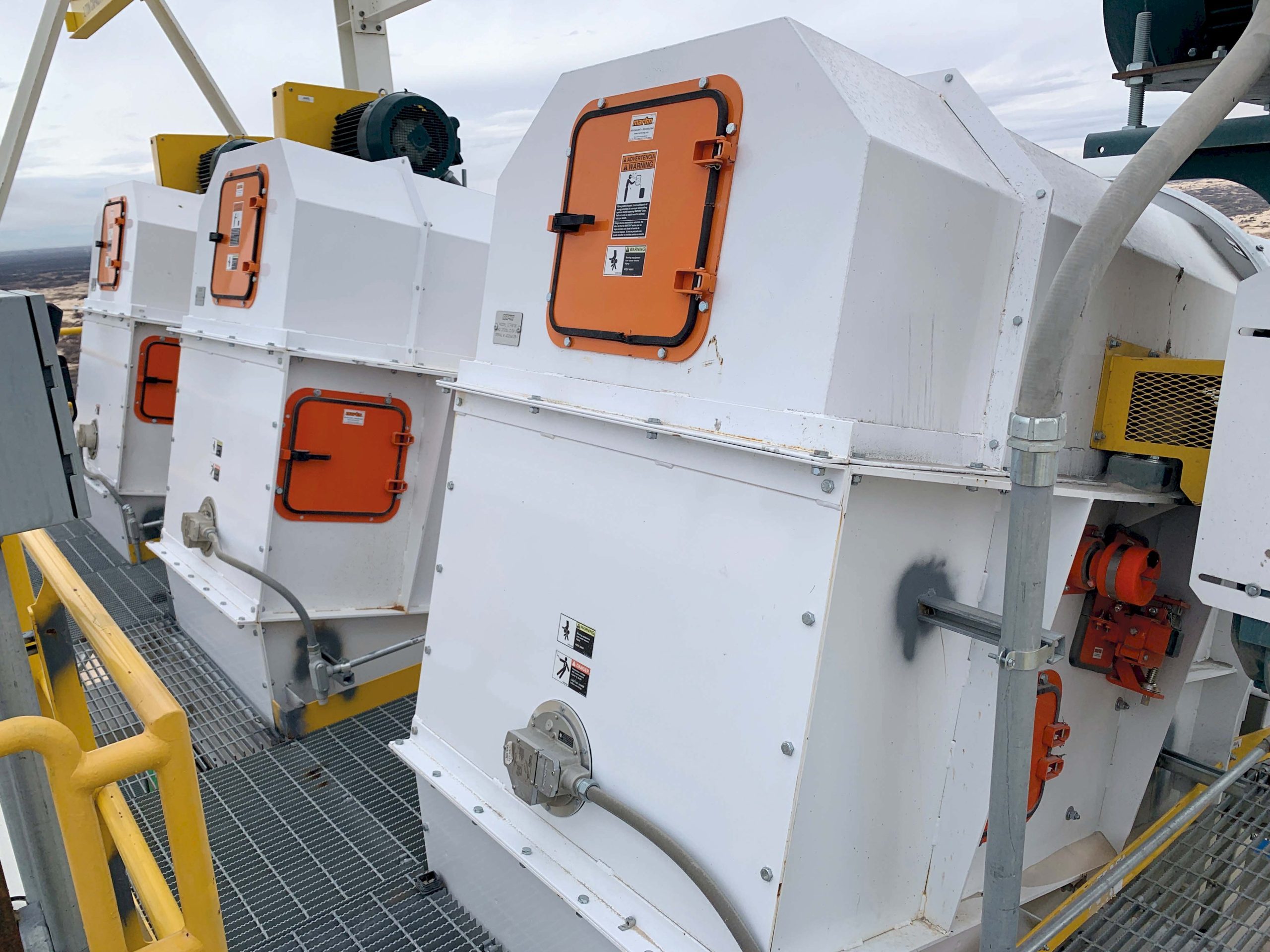
Strategically positioned access hatches facilitate control and service.
Access hatches can sometimes be placed in awkward places where they provide very limited visibility, or they can be kept too small to allow inspection or maintenance. Conveyors are sometimes positioned so close to the floor that it is not possible to get under the conveyor for cleaning. It may also be impossible to access the platform and drive element locations around the head drum for proper inspection or maintenance.
Suggestion: Follow the recommendations in CEMA’s Belt Conveyors for Bulk Materials publication, 7th edition, for access conditions and clearance values.
5. Blocking of Essential Points with Pipes and Cable Trays
The structure carrying the conveyor provides suitable space for the installation of power line, plant air pipes or water pipes. Violation of position controls of electrical and pipelines installed in the conveyor structure is a common occurrence. These pipes and power lines often complicate the installation and servicing of critical elements such as belt travel switches, belt scrapers, v-scrapers, and return rolls.

This cable channel prevents efficient replacement of the rollers.
While electrical and pipelines rarely need maintenance or replacement, the components around them are often subject to frequent inspection and service. Moreover, these lines are often located on walkways that would normally have been built to provide access to the conveyor.
Suggestion: Make it a design requirement that electrical and pipelines do not block access to critical components along the conveyor. In the head drum and tail drum section, the connections from the electrical and pipelines to the conveyor components must be of the flexible type.
6. Insufficient Edge Sealing Distance
The free belt edge outside the skirtboard in the loading zone of a conveyor is called the edge seal distance. The CEMA standard requires that the distance between the inside dimensions of skirtboards be equal to 2/3 of the flat belt width, regardless of trough angles. The European standard prescribes an equation for the free belt edge. The standard belt edge is used in capacity calculations to prevent the material from falling from the edges of the belt in the area between the conveyor rollers. None of these current standards provide sufficient edge distance to accommodate the belt centering and sealing systems needed to meet today’s dust and debris control requirements. The free edge distance should be determined by the distance required to properly seal the belt. Belt centering allowance mostly depends on conveyor structure and drum face widths. Belt width has no significant effect on belt centering margin.

The free edge distance should be determined by the distance required to properly seal the belt.
Suggestion: The free belt edge separated to seal the belt and allow for belt slippage should be at least 115 mm regardless of the belt width.
7. Inadequate Chute Design
Chute design has evolved in recent years with the use of Discrete Element Modeling (DEM) programs. However, many shots are produced from sketch images rather than detailed design. However, Discrete Element Modeling analyzes may yield worse results than using the generally accepted old rules-based design methods if the bulk cargo properties are not properly defined.

There are aspects of modern loading zone design that focus on both safety and production efficiency.
Even if the bulk material is correctly specified, it is common for the design of the structure supporting the chute and drums to ignore the access requirements for the intended use and rely purely on ease of fabrication and assembly. A type, one-foot vertical head drum frame generally provides better reach than a table-type frame.
Suggestion: Test the bulk load and base the features that represent the worst-flow scenario to design the chute using Discrete Element Modeling. Design the supporting structure
so that it does not block access to critical components and allows adequate access for maintenance operations and future upgrades.
8. Insufficient Belt Cleaning
As the requirements for dust and spill control are becoming more stringent, it can easily be concluded that there will be a need for more elaborately designed belt scrapers in the future. Often an insufficient number of belt scrapers or lighter-duty scrapers than required are selected. In addition, the space provided in the design may be insufficient to properly install and service the belt scrapers.
Suppliers are under pressure to meet their price targets and therefore may procure equipment they know will not meet expectations. The trick here is to put pressure on the supplier by making specification terms relatively vague with terms like “or equivalent”. In this case, the supplier is forced to choose between meeting the price or placing a simple design and the solution of this problem on the customer.

Ensuring sufficient space and access for more than one scraper is critical in terms of preventing the material from being transported back and controlling the leakage material.
Suggestion: Include belt cleaning performance specifications when determining conveyor design requirements. Allow sufficient space for the sweeper conveyors if the space provided by the head chute design is not sufficient to fit at least 3 scrapers and if the carryback material can be held in a drip chute with nearvertical walls.
9. Compromising Belt Width for Rapid Movement
Conveyors are generally designed to travel at speeds of 7.5 to 11.5 m/s. In some industries, maximum conveying speeds have been set to limit spoilage of bulk cargo or control dust. Based on practical experience, these applications are often stretched to meet price targets. The amount of dust and debris is directly related to belt speed and tonnage. On the other hand, wear is a function of the square of the bulk material flow rate. The balance between width and speed must therefore be carefully considered.

The amount of dust and debris is directly related to the speed and tonnage of belt
Suggestion: Follow the recommended maximum conveying speeds listed in the 7th edition of CEMA’s Belt Conveyors for Bulk Materials publication. Apply a factor of safety in the direction of keeping the conveyor speed low or keeping the conveyor size high.
10. Not Allowing for Upgrading Process
When it comes to upgrading a system, the first thing that normally comes to mind is to increase the tape speed. With the exception of the drive components and a few other elements, increasing the speed is considered sufficient to increase the amount of material conveyed per hour. An upgrade that involves simply changing the velocity will usually result in a decrease, rather than an increase, of hourly conveyed material, for example due to clogging problems due to a change in material path, or when the existing chute section creates a flow restriction. Many designs leave no room for even reasonable upgrades or additions. With minimal effort at the design stage and little or no additional fabrication or assembly cost, some latitude can be provided for upgrades to improve system performance.

Servicing and upgrading is extremely difficult as this conveyor is placed very close to a tunnel wall.
Suggestion: You can use standard components to meet price targets. But to meet production and cost targets, you must make room for upgrades to address future design issues.
A New Hierarchy in Conveyor Production
Conveyor equipment manufacturers have begun to use a new hierarchy for design decisions that could revolutionize conveyor architecture. The priority of design decisions is determined according to the following hierarchy:
1. Capacity
2. Safety and Compliance with Law
3. Leakage Material Control
4. Streamlining Service Operations
5. Affordable Cost
6. Upgradeability
Moving from a “traditional” conveyor design to a new conveyor architecture can result in significant improvements in environmental performance and production efficiency.
Conclusion
The consequences of basing the purchasing decision solely on price while ignoring problem areas are often less than target hourly material transported, higher operating and maintenance costs that are over budget, and reduced safety. All of the measures to address these issues can be justified by arguments for life-cycle costs and avoidance of additional costs if they are addressed at the feature specification and design phases. Design issues that are carried through to manufacture, installation, and use are now either completely unfixable, or the cost of fixing them is substantially higher than in a scenario where they were addressed and financed earlier in the project.

")

