


Emrah ÖZTÜRK
Kalyon Kolin Cengiz İnşaat J.V. Gayrettepe – İstanbul Airport Metro Construction Project, Civil Engineer , İSTANBUL, 2022
Engin SÜRÜCÜ
Kalyon Kolin Cengiz İnşaat J.V. Halkalı – İstanbul Airport Metro Construction Project, Senior Civil Engineer , İSTANBUL, 2022
Assoc. Prof. Hasan YILDIRIM
İstanbul Technical University, Civil Engineering, Construction Materials Department, İSTANBUL, 2022
1. Introduction
Abstract
The works of tunneling with the method of TBM (Tunnel Boring Machine), which is the most effective and specific tunneling method, are frequently used in the global literature and practice currently, and the use thereof has showed a significant increased for the last 10 years. The works of combating the water in the tunnel and draining the water from the tunnel are at the top of the list of the most difficult problems in tunneling practice. And this reveals the chemical and physical conditions that may damage the reinforced concrete structure inside the tunnel. The struggle against water in the TBM tunnel practice is mostly because of the points of junction of the precast elements, rather than the water flow from the inside of the reinforced concrete structure. The mortar mixture that is called TBM backfill grout is an element that will fill the gap between the segment and the natural ground during the TBM excavation and increase the water impermeability between the segments, in addition to providing the stability on the ground. Rubber-based gasket elements that are positioned both along the tunnel and within the ring between universal segments are the most important sealing material in the tunnel, as it ensures this impermeability with its design and constitutes an elastic structure between the reinforced concrete parts during assembly. In addition to these elements, in order for the segments not to separate from each other along the tunnel during the assembly, for ensuring putt-out and shear force in the case of segment console, and for taking the shear loads within the tunnel eleafter the assembly, there also the design of the elements called bi-block or pin. The gasket and bi-block elements in the alignment of the universal segment also have an effect on each other in addition to their own functions. While choosing bi-block elements, through experiments, it has been evaluated that the bi-blocks directly affect the impermeability and how this connection is established. This issue has been taken into consideration in the Gayrettepe 3rd Airport Metro Project, the construction of which was commenced in 2016 and which was put out to tender by the General Directorate of Infrastructures, Ministry of Transportation, Republic of Turkey (AYGM), and the projects, the construction of which was undertaken by Kalyon-Kolin-Cengiz Construction Partnership, which actually commenced in 2018 and which was put out to tender by AYGM, and with the trials, tests, and calculations made in the scope of the project, the association between this connection was more carefully evaluated.
In the world and in our country, giant tunnel works are quickly completed and commissioned with the TBM tunnel boring machines. In these commissioning process and after the operation, the challenge against water and/ or tunnel impermeability take(s) a long time and create(s) additional cost. The costs of the chemical injection made between the tunnel and ground and the costs of cement/ mineral additive-based backfill vary depending on the tunnel dimensions and exceed millions of dollars. Water leakages within the TBM tunnel are mostly caused by the
points of junction of precast segments. The gaskets, which are positioned in the area where the grooves left between the segments are and which surround the segment all around, are designed to ensure this impermeability. The geometric dimensions of the gaskets and particularly the fact that they tightly surround the segment are the most important factors. However, this process may turn into assembly defects under the site conditions. Apart from faults committed during the longitudinal assembly of the gaskets, there is also an assembly error made by the TBM
erector (segment assembly) operator at the start of these problems. The requirement to take into consideration this sort of defective assemblies during impermeability tests has arisen, and with the tests conducted, the tests of gaskets under pressurized water, these offset assembly defects have been evaluated in the laboratory environment. In order to stay at the safe side, the water pressures to be applied on the gaskets have been taken as 2 times of the operating pressure to be applied to the segments during operation. Despite staying in the safe side to such an extent, the fact that there is water impermeability in the tunnels has clearly revealed that there will be a defect. It has been seen that by taking the shear forces of the bi-blocks that are the guides in the segment assembly and meeting the pull-out load of the console segment by creating moment load and when the ring assembly is initiated after the excavation, with the repelling force applied to each other by the gaskets showing an elastic behavior and with the load to come from this load, the distance between the gaskets is tried to be opened. It has been shown that this repelling force between the gaskets apply repelling – pull-out force to the bi-blocks and tries to tear off the pins within the segment. These pins are assembled as embedded element during segment concrete casting. The effect of the relationships of these forces with each other on the water impermeability within the tunnel have been evaluated in this study.
2. Evaluation of the Tests
2.1 The water pressure on the gasket and the tests
conducted for this pressure
According to thee feasibility studies conducted on the tunnels, the operating pressure was at the level of 6 bars, when it is checked based on the underground water level and physical properties of the ground. For the water pressure impermeability tests among the gasket physical tests, in order to remain in the safe side, Pemn coefficient was taken as 2 in the technical specifications of the project. This value corresponds to the water pressure in the most inconvenient section of the project, but despite that, tests have been evaluated over 12 bars. According to the norms and test standards of STUVA, the international research and laboratory company, Load-Displacement and Water Impermeability tests have been conducted. In these tests, it was applied by taking into consideration of cases of 10 mm offset in total and tightening of 6mm gasket (2 mm packer) according to the relevant STUVA norm (Figure 1).


In theory, segment surfaces may overlap, but this situation causes damages in the form of breaking in the sides and corners of the concrete on the segment during the physical assembly. In that case, before the TBM segment assembly, the material called packer (of 2 mm thickness and of the quality not to tighten) is placed from the segment surface on to the ring surface. Therefore, while measuring the elastic shape changing, which is the elastic return force, in the load displacement graph, the gasket’s entrapment gap was taken as 6 mm, rather than
8 mm, as can be seen in the Figure-1. The case of the gasket with 10 mm offset is the indicator of the most inconvenient assembly. Because the segment assembly tolerance values are maximum 5 mm in the project, this offset defect of 10 mm is a situation to stay on the safe side. This case without offset is more clearly seen in the Figure-2. Packer of 2mm is applied to a thrust surface of the segment, and before the assembly, it remains as a distance of 6mm+6mm = 12 mm from the segment surface (or gap of 32 mm from a groove to another) and after the assembly, as 10 mm (in other words distance of 22 mm from a groove to another).


The 100% entrapment situation in the Figure-2 arises as a result of the full leaning of the TBM thrust cylinders on the segment after the segment assembly with TBM erector. The ending of this situation, on the other hand, will arise while creating a space for the segment for the next ring and pulling back the thrust during the next ring assembly after the TBM excavation. Here, mutual gaskets will push each other and the distance between the gaskets will try to open with this repelling force. Gaskets will apply a load depending on their elastic return forces. The dowels to meet this load are called bi-block or pin socket.
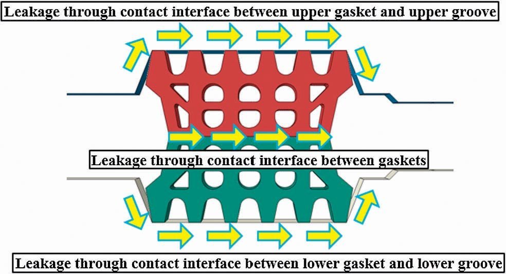
As can be understood from the Figure-3, it can be seen from which sections in the gasket junction surfaces shown in the Figure-2 there will be water flow.


At the same time, with the graph seen in the Figure-1 of a different brand of a different project showing the similar applications’ offset, gap, flat corner, and real corners, there is a pressure displacement test mechanism.


STUVA tested the above-summarized working principle independently from each other, and left it to the engineer who made the application to evaluate the results. Because each test may lead to a different pressure value and different force. The production frequency changes on the gasket production line, such as the mixtures of the products from the production line, their press pressures, product prescriptions, ambient temperature, and press temperature may change these test values. Therefore, by taking into consideration these changes and mass productions on the production line, it is tried to minimize the process of its becoming irreversible with these
tests and challenge against water with the chemical injection method in the future.
2.2 Examination of the Water Impermeability Test and Test
Diagram
In relation to the water impermeability test, STUVA says that a test mechanism on the gaskets available in the figure given in the Picture-3 must be used and it must be tested for the desired pressure value.


After the test mechanism is prepared, the gasket, which has been designed with 0-5-10 mm offsets and the molds of which had been prepared and the casting of which had been realized before, is placed on the system, and the system is closed. Then, it is tested in the desired pressure or higher pressures. The Graph –1 shows one of the results of the test where the gaskets in the aforementioned projects were used. When we examine the graph of the gasket, which was prepared according to the Stuva test plan and mechanism and the test of which was completed, it provides us with information about the 0-5-10 mm offsets and pressuregasket gap. Our most inconvenient section according to Stuva, our 10 mm offset operating pressure will be compared with 12 bars that is 2 times of 6 bars. The test mechanism was placed on two brace profiles seen in the Picture-3, and the area created as a result of the junction of two braces models for us the longitudinal gasket junction. A 2 mm gap is left in this interim distance, and the segment defines the surface where the longitudinal assembly, that is where two ring combines. On the other hand, the other surface area models the combination of the segments within the ring. Here, in 12 bars, including 2mm packer, it allows a gap of 6.2 mm as can be seen in the Graph-1. Thus, in another way of saying, the segments, which are described in article 2.1 with the 2 mm packer gap and which is supported by the thrusts in the Picture-2, can be bored in 4.2 mm, excluding the packer, when the assembly of the second ring set starts as a result of releasing the thrusts. The fact that the gasket bored as 4.2 mm will ensure water impermeability in 12 bars will be valid for the 2-fold safer and the most inconvenient assembly position.


Let’s examine the Graph-1 in more detail and interpret it. When it is assumed that the assembly was made with the zero assembly tolerance and the operating pressure is taken into consideration, it allows boring a gasketof around 10 mm including 2 mm packer in 6 bars, that is, of 8 mm. Therefore, it can be interpreted that working 2 times more safely and evaluating the issue with the offset of 10 mm does not actually constitute a case of overdesign. Taking the operating pressure as two times is a relevant decision in terms of design.


As can be seen in the graph, the case of 5 mm offset stays in a closer parallelism with the graph with 10 mm offset. It is observed to remain at almost the same displacement point in 12 bars that we taken into consideration. This shows that the gasket placement with offset increases the water impermeability limits.
2.3 Load-Displacement Test and Examination of the Test Results
Like the load displacement test, the gaskets obtained from the factory production are tested according to the norms and declaration of Stuva. The test mechanism and the details of the mechanism are given in the report titled Ref: Stuva 54 Forschung+Praxis: RecommendationforGasketFrames in SegmentalTunnelLining. The gasket is placed on the mechanism seen in the Figure-4, and the push-back force values of the gasket under the load displacement curve are read.


The load displacement curve test was read on the gasket produced at the same time and obtained from the same gasket sample. Therefore, the sample, on which the Water Pressure test was made, and the sample, on which the Load Displacement test was made, are the same, and in order to make a linear evaluation, it must be obtained from the same sample on the same production line. The Load-Displacement curve is given in the Graph-2. The tests have been completed with the offsets of 0-5-10 mm and according to the Stuva mechanism and disciplines in terms of evaluation.
When the Graph-2 is examined, while the water impermeability in the section with offset within the water pressure graph is less than the case without offset, it is higher in the case without offset. In this case, taking the push-back force where there is no offset, that is, where no assembly mistake was made, in another way of saying, the returning force, according to the 0 mm offset will allow us to remain on the safer side. Therefore, here, that value with offset that we will read in the Graph-2 is seen in the Graph-3 as well.


While reading the graph direction after taking the water pressure in the Graph-1 as 12 bars, which is the two times of the operating load, and while reading the graph direction in the Graph-3 from 6.1 mm, which is the gap value in offset 10, 12 bars (we have given the gap with packer) and from 6.1 mm, including that packer, it is required to go towards the linear load pushed back. In case that we take it from Offset 0 mm, as we described above, it will be exposed to a higher linear load value. In this case, in the Graph-3, a linear load value of 21kN/m is read.


However, the value read in the Graph-3 is a stress pushback force valid during the assembly and years following the assembly. In the pressure reduction section of the Technical Specifications Gasket System Tests articles in the projects, the issue that the stress relaxation value 100 years after is less than 50% is written, and it is also written in article 5.7 of Stuva that it is less than 45% in the stress relaxation test.
Specifications Gasket System Tests articles in the projects, the issue that the stress relaxation value 100 years after is less than 50% is written, and it is also written in article 5.7 of Stuva that it is less than 45% in the stress relaxation test.


As long as the details of this test and content of the graph meet the values in the relevant specifications and norms, it will not affect the relationship between the Gasket and Bi-Blocks. Here, the only issue to affect is the reduction of the gap criterion by 50%, in this case where it is allowed to stress relax by 50%. In this case, the Graph-3 will turn into the Graph-4 as below.
As can be seen in the Graph-4, in case of 3.05 mm gap in the offset 0 mm value, an elastic returning force of 39 kN/m will be observed in a load loss of 50%.
The pressure reduction test arises due to the result of a test that takes 3 months. In the reduction of this value pressure of 39 kN/m in the Graph-4, the loss of 50% in the Technical Specifications or the loss of 45% according to Stuva can be taken into consideration. However, in reality, taking the real loss value after conducting this test and finding the Load Displacement 0 mm offset value will mathematically provide us with more realistic results.


The graph of the 3-month pressure loss after 100 years on the sample from the same mass production and from the same line with the gasket sample, the above Load-Displacement and Pressure-Displacement results of which we reached and the test results of which are given below, is seen in the Figure-5.


The graph of the 3-month pressure loss after 100 years on the sample from the same mass production and from the same line with the gasket sample, the above Load-Displacement and Pressure-Displacement results of which we reached and the test results of which are given below, is seen in the Figure-5.
We see that this value in the Graph-5 was drawn by taking into consideration the loss of 44.4%. If we accept that the gap of 6.1 mm is lost with 44.1% and after 100 years, it gives this reaction according to the Figure-5, we can check the load value in the displacement of 3.34 mm.
It is seen that the values found in the Graph-4 and Graph-5 are taken into consideration in the bi-block pull-out tests in some sources. However, it tries to release bi-block only during the assembly of the segments. Thus, the gaskets that are entrapped in the size of the packer thickness in the thrust forces of the thrust cylinders remain like that during one TBM excavation. Then, after the excavation is completed, the thrusts are pulled back according to the segment assembly. The gasket’s will to release itself that arises after the cylinders are pulled from the segment
side surfaces, which is the elastic returning force, will arise. On the other hand, in this instantly arisen force, bi-blocks must meet this force, and during this meeting, the allowed pressuredisplacement and load-displacement curves must be taken into consideration. The criteria to be taken into consideration are the 10 mm offset in the Graph-1 and 0 mm offset in the Graph-2. Graph-4 and Graph-5 are not the graphs that must be taken into consideration in this comparison.


2.4 Bi-Block Pull Out Test and Examination of the Tests
ıf there is no different case in this sort of tunnels, in the biblock elements, the pull-out force due to the push force from the gasket; shear force due to the static situation; and bending resistance force due to the console situation in the last ring placed on the tunnel ceiling arise. From these forces, the gasket push force, which is the force that affects water impermeability and the relationship between the gasket and bi-block, will be examined with a test.
In article 2.3, we have calculated with the nominal and test results that the force that we will finally take into account is 21 kN/m and the opening is 6.1 mm.
The unit of this linear load coming to the segment laterally is kN/m. The element to be tested cannot be tested serially. Therefore, the value of the load applied to a single block must be found. The value that cannot be opened, on the other hand, is the same in all bi-blocks. It must not be opened more than 6.1 mm.
By considering the detailed segment drawings, bi-block numbers, and gasket center circular effect length applied in the projects, we can find the value of the load applied to a bi-block.
As can be seen in the Figure-6, there are 16 bi-block elements of equal dimensions and geometry on a ring set. These biblocks in the segment of 5-1 precast in total are the elements that would take the pull out force in the gasket within thering set. When the details of the bi-blocks are considered, it is important to use polyamide elements reinforced with glass fibers in terms of being brittle and staying longer in the elastic region.
These bi-block elements consist of 3 parts. The photograph on the left side of the Figure-3 shows the mechanism during the pull out test. The photograph on the right, on the other hand, shows the situation after the test. First of all, bi-block pins are placed into the test equipment. Then, the socket is manually placed on one side of the test system. The socket does not fully enter the dowel by hand and is left as it is. Then two sections are placed under the press machine for the assembly of the dowel on the other side, and the sockets are assembled in the manner to model the TBM erector’s segment assembly under the press machine by force. At the same time, in this detail that models the two segment bi-block area, packers of 2 mm are placed in between. Because, as already known, the displacements in the gasket mechanism described in article 2.1 include this part of 2 mm. Therefore, the purpose is to try to model the current situation during the press and shear tests. The most important issue in the modeling of the assembly is to damage both the pin and the female and male threads of the socket
The gasket is located in the geometry close to the convex part of the segment. The distance between the middle of the segment and the gasket axis is 3.105 meters. Therefore, the circumference of the gasket is 19.5 meters, when the axis of the gasket is taken into consideration.
Because the total gasket surface is 19.5 m, if the total linear force applied to the gasket is F=21 kN/m, the total force to affect the total gasket circumference will be 409.5 kN, and it will be applied to 16 bi-block sets in total. The force to be applied to 1 bi-block will be 25.59 kN.
3. Material Features
3.1 General Features of the Bi-Block Material
With the experiments made, it has been decided to try the bi-block material with a polyamide-based material. In the physical experiments for the material features, it was taken into consideration that the elastic deformation must be low and plastic movement must show a brittle behavior. When the material is subjected to shear tests in the first stage, it was tried as polyamide, and both the dowels and sockets were used in this manner. The material showed a ductile behavior, and it was observed that when the socket is stripped from the dowel, it remained very little in the elastic region and the threads of the dowel gradually separated from the sockets by showing a plastic behavior. As a matter of fact, the material deformed in each thread, and there were gradual increases and decreases.
This situation revealed the requirement that the polyamide material has to be reinforced. Because the physical feature sought is the elastic brittle behavior and minimum deformation under the load.
The polyamide reinforcement was tried with glass fiber reinforcement, and a polyamide with 30% glass fiber reinforcement was utilized. When it was tested again, it has been observed that it was more brittle than the one where polyamide was used and that lower deformations occurred under higher forces. The above-requested load deformation curve has not been reached.
It is observed that the requirement for the material to be brittle requires the increase in the glass fiber reinforcement of polyamide. However, the glass fiber reinforcement will remove the material’s economic aspect. Within this context, it has been anticipated to add steel material into it. First of all, 14-16mm ribbed S420 class construction iron has been added. Because construction iron is a material that is ductile and shows the behavior of soft steel, it did not affect the results.
Then, likewise, 1050-type steel of 14 and 16 mm diameter, which is more brittle, has been used. In the experiments made with type of steel, it has been observed that the material works under a higher force in very low deformations.
3.2 General Features of the Gasket Material
The geometrical dimensions of the gasket are given in the projects, just as the case with bi-block. At the same time, hardness, tensile strengths, tensile elongations, deformations, water or oil absorptions, ozone resistances and the rate of change of these values after aging have been limited by standards and specifications as well. Its main component is high-density petroleum-based polyethylene, which is called HDPE. In addition to physical features, this polymer is a material that is resistant against environmental impacts and that has a high molecule mass. When utilized in tunnels, it can be produced in geometries that will affect the manner it works under different pressures and its resistance to water pressure, with its perforated structure. This is an issue which can be optimized depending on the tunnel needs.
All tests to be conducted on the gasket material must be made on the samples selected from the site. This not only will increase the quality assurance of the gasket, but also will give the real values on the impermeability test in particular. The results obtained from the gasket with all test samples are given in the Table-1. The tests conducted on the EPDM Gasket in accordance with standards will provide information about the gasket specification.
3.3 Conducting the Bi-Block Tests According to the Gasket Test Results and Evaluation of the Results
The important factor in the bi-block tests conducted in the Istanbul Technical University’s Construction Material Laboratory is the presence of the load-displacement graph. Because the real importance issue is not the maximum load that the bi-block bears. Allowing the gasket to open within the allowable limit is related to the displacement value in the bi-block. There fore, it is very important for the tensile device used to measure the deformation with an accuracy of 1/10 of a mm and to instantly display it graphically on the screen, and that the test gives us the result at that moment. Secondly, modeling the test explained in Article 2.4 according to the situation in the site, which is the utilization of the lower part of the tensile test device as a press at the same time and the utilization of the same device as a press in the shear test, gives us the load-displacement diagram in the shear test, despite the fact that we do not need it. As seen in the Picture-3, the feature tests of the relevant products have been conducted multiple times as described in Article 3.1. Lastly, the P6 material with 30% glass fiber and 16mm grooved 1050 steel was used. This conclusion has been reached in all trials made in a composite working principle for the material to work under both shear and tensile loads.
Below Graph-6 is the test result. First of all, let’s examine the graph. When we examine the graph, we observe that it is more than 70 kN on 3 samples in a displacement of 10 mm. The maximum load is not an issue of interest for us in this test. Because our maximum limit is 6.1-2=4.1 mm. After it exceeds 4.1 mm, it means that the gasket is leaking water, even if this value is very high.
The values, which must be checked in the graph and the table summarizing the graph must be the following.
Is the displacement at the force applied by the gasket to the bi-block at or below the allowable limit, or is the load applied by the gasket to the bi-block at the allowable displacement limit more or less than the load calculated?
Within this context, what we are looking for in our test is 25.59 kN. How many mm of opening is of issue at 25.59 kN? It is seen that there is an opening of 1.5-2 mm approximately. On the other hand, this can also be checked: When we say, “How much load has it been subjected to at 4.1mm?” 4.1mm of opening occurred against a load of more than 43kN approximately.
4. Evaluation of the Results
Several bi-blocks and gaskets are utilized in various projecs. Projects utilizing segments are used in structures with numerous requirements, such as subways, various mechanical shafts, wastewater projects, rainwater projects, and highway railway tunnel projects.
In some construction elements, it not even required to take into consideration the water impermeability. Particularly in cases where there is no permanent structure or the limit of water in take from outside (for example, wastewater projects) is not highly essential, the above-written criteria, safety coefficients and evaluation should be evaluated and changed based on the project conditions and requirements. However, such as in the subway, particularly in cases where electromechanical effects (electrical resistance, leakage current, damage to team equipment, etc.) have to be taken into consideration, particularly in end use, water impermeability is the case that requires attention. Under the current circumstances, costs are assessed over the triple elements of time-safety-quality in the construction sector, as in the other sectors. When the issues of costs, marginalism, individuals’ maximum benefit / maximum profit and minimum spending and minimum costs, which are among the principles of economics, are taken into consideration, the impact of the materials to be chosen on the work to be performed will be highly important.
ointly evaluating the two elements in this study and examining the results, preventing the water flow, which is the biggest problem in the tunnels when the final product comes out, and fighting against water last for years, and it has a great impact both on the commissioning time and during the operation.
Here, the importance of the joints, which are as important as the pre-cast reinforced concrete structure in TBM tunnels and which are found in approximately every 1-2 m², will also be revealed. In the above depicted bi-block gasket relationship, engineers may increase the safety coefficient even more depending on the importance of the structure. However, this has to be evaluated over the economic solutions and benefit-cost impacts.
In the feasibility studies and anticipations, the static water pressure was taken into consideration according to the conditions of the ground, and the water pressure of 6 bars (taking into consideration the worst case along the whole line) has been evaluated according to 12 bars. Offsets have been taken into consideration according to the most inconvenient cases thereof. At the same time, during the tunnel excavations, it was seen that the TBM mirror pressures were at the levels of 3.5-4 bars at maximum. When the results are evaluated, it is seen to be on the very safe side. Factors of safety and over design issues have to be reviewed according to usage conditions and project requirements, by taking into consideration these results.
In line with the above-written mathematical and physical results, the materials utilized in the projects were examined, the importance of water impermeability and the relationship between the tests performed on the two most important elements were examined. Taking this relationship into consideration, when both projects are examined, a total of approximately 110 km of TBM tunnel construction is being performed, and a total of 73 thousand ring sets have been assembled, and along the tunnel, there are 73 thousand gasket junction surfaces and around 438 thousand gasket compositions in the transverse direction. There is a gasket surface composition of approximately 2000 km in the tunnel transverse and longitudinal directions. At the same time, more than 1.1 million pieces of bi-block elements are used along the tunnel. With respect to the water impermeability, both projects are highly successful in the TBM tunnel. With respect to structural sense, this success in the points of junction related to both TBM tunnel backfill injection, selection of bi-block and gasket elements, tests, test frequencies, production controls, assembly controls, briefly all quality control processes.
In order to ensure water impermeability, engineering groups in the global literature continue to work on many insulation methods with respect to sustainability and cost. More economical and sustainable solutions will bring more efficient results and will ensure progress through different design solutions.
REFERENCES
[1] B.Maidl, M. Herrenknecht, U. Maidl, G. Wehrmeyer, MechanisedShieldTunnelling. Berlin, 2012.
[2] STUVA, Forschung + Praxis 54 RecommendationforGasketFrames in SegmentaltunnelLinings, Köln, 2019.
[3] TBM Line Tunnels Gayrettepe İstanbul Airport Metro Project Segment Interior Coating Technical Report, İstanbul, 2018
[4] TBM Line Tunnels Halkalı İstanbul Airport Metro Project Segment Interior Coating Technical Report, İstanbul, ……
[5] C. Gong, W. Ding, K. Soga, K.M. Mosalam, Failure mechanism of joint waterproofing in precast tunnellinings, 338
[6] Guide for Precast ConcreteTunnel Segments ACI 533.5R-20
[7] S. Fabozzi, Behaviour of segmental tunnel lining under static and dynamic loads, 2017
[8] M.Bakhshi, V. Nasri, , TunnelSegmentGasget Design – Solutions andInnovations , Canada 2017, 6
[9] C gong, K Soga, WQ Ding, K Mosalam, Sealant behaviour of EPDM gaskets in TBM tunnel segment joints, USA, China, 2017


")
